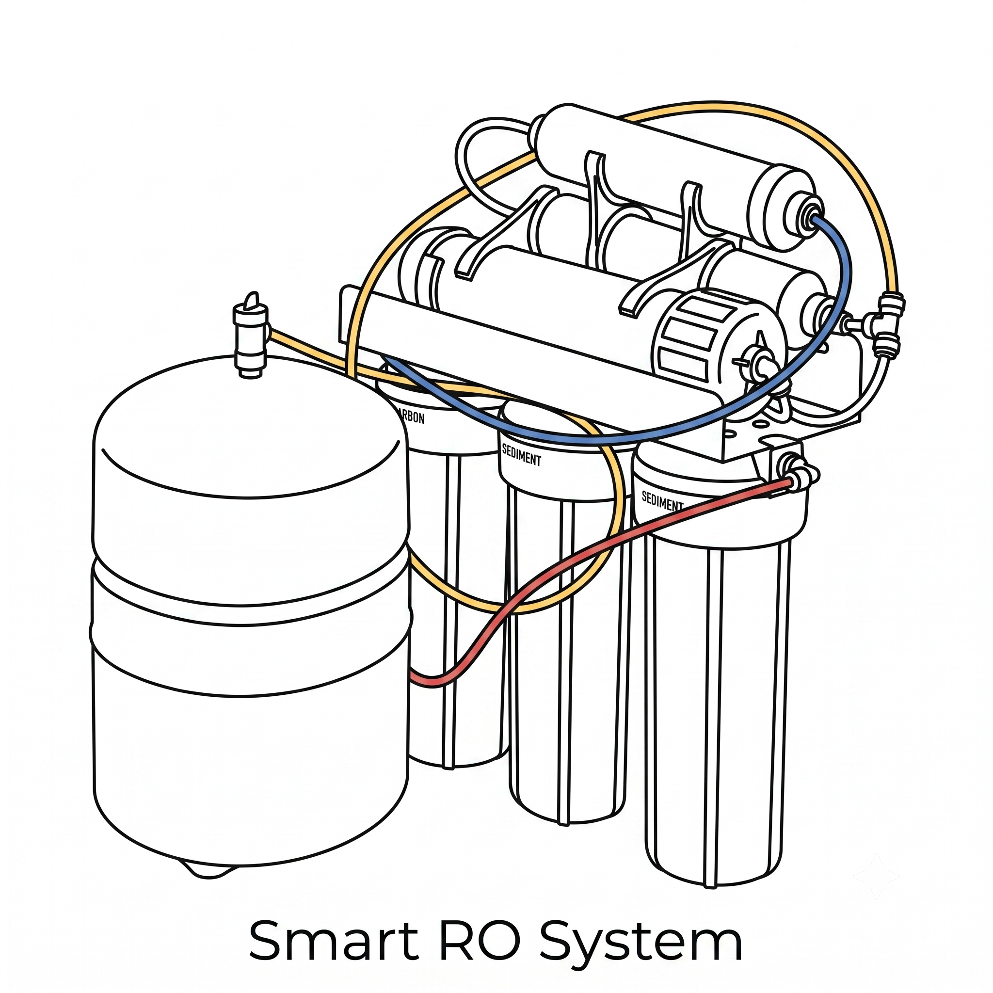
Remineralized or Pure RO water? Why not both.
Having remineralized water for everyday drinking was nice, but I kept running into situations where I needed Pure RO water instead. I use it in humidifiers and steamers to reduce mineral buildup, as a neutral starting point for making coffee water, and for mixing cleaners and other household solutions where I do not want extra minerals changing the result.
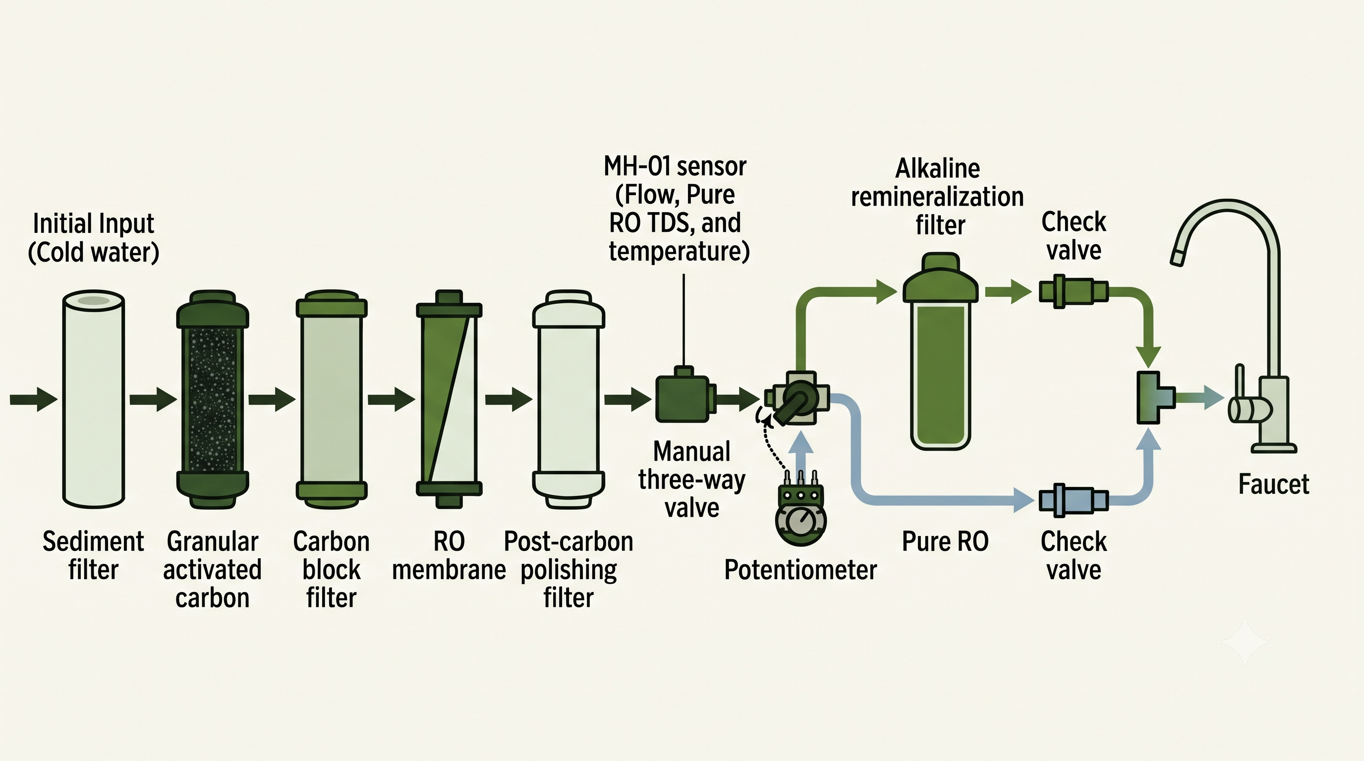
Most remineralizing RO systems send all product water through a final alkaline or mineral cartridge. I wanted the same system and faucet to provide either option, so I added a three-way valve after the system's final filter but before remineralization. One path passes through the remineralization cartridge, while the other bypasses it and stays Pure RO. I can also leave the valve somewhere in between when I want a lighter mineral taste.
This approach should work with many standard under-sink systems that have an accessible remineralization filter. The Smart RO monitor reads the valve position, tracks which type of water is being dispensed, and adjusts remineralization-filter usage accordingly. It also tracks overall water use and Pure RO TDS so filter replacement estimates respond to actual use and system performance instead of relying only on calendar schedules.
What It Does
The Arduino monitors:
- Current water flow in mL/s
- Pure RO TDS
- Water temperature
- Pure RO, remineralized water, or the approximate mineral-water mix
- Estimated life remaining for the sediment, granular activated carbon, carbon block, RO membrane, post-carbon, and alkaline remineralization filters
It saves usage and calibration data when power is removed. The display turns off after five minutes, then wakes when water flows, a button is pressed, or the valve is moved.
Parts
Electronics and plumbing
- iSpring RCC7AK reverse osmosis system
- Arduino Nano with ATmega328P
- 0.96-inch SSD1306 128x64 I2C OLED
- DS3231 real-time clock with backup battery
- MH-01 six-wire flow, TDS, and temperature sensor
- Gravity analog TDS board
- B50K potentiometer
- 81k or 82k resistor
- Three tactile buttons
- Small piezo buzzer or speaker
- 1/4-inch L-port three-way ball valve (exact valve used)
- Two 1/4-inch check valves
- One 1/4-inch T-junction
- Extra 1/4-inch RO tubing
- Breadboard or solderable board, wire, headers, and USB power
- Handheld TDS meter
Printed-part assembly hardware
- 1 x M3 x 25 mm screw
- 4 x M3 x 10 mm screws
- 4 x M2 x 15 mm screws
- 4 x M2 nuts
- 4 x M2 rubber washers
- 6 x 1 mm M3 heat-set inserts
- 1 x 10 mm washer
- 3 x M3-size self-tapping wood screws
Plumbing Layout
The MH-01 goes after the post-carbon polishing filter but before the alkaline remineralization filter. This lets it measure all dispensed water while still reading the Pure RO TDS before minerals are added.
Wiring
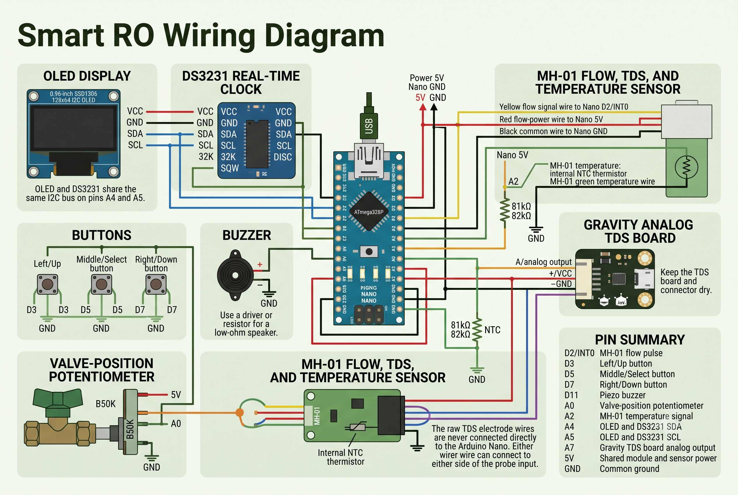
Everything must share the same ground.
-
For the temperature divider, wire
5V-> 81k/82k resistor ->A2node -> MH-01 green temperature wire ->GND. - The MH-01 red wire paired with the blue electrode wire connects to the Gravity board probe input. The other red wire powers the flow sensor.
Build and Installation
-
Prepare the printed parts. Download and print the Smart RO model from MakerWorld. Put two M3 heat-set inserts into the upper holes in the base beside the post, two into the holes on the underside of the base, and the final two into the handle assembly. Keep each insert square and let the plastic cool fully before adding screws.
-
Assemble the valve mechanism. Press the three-way ball valve firmly and evenly into the base. Drop the 10 mm washer into the handle slot, align the linkage, and secure it with the M3 x 25 mm screw after the inserts have cooled. Point the long end of the valve straight up so the valve and base form a
+shape when viewed from the front. Press the handle onto the valve stem; in the correct starting position, it points to roughly 4 o'clock. -
Install the potentiometer and clamp. Solder the potentiometer wires before pressing it into the clamp, aligning its locating notch with the groove. The friction fit is usually enough, but a small amount of non-conductive adhesive can be added if needed. Slide the clamp through the post on the base and fasten it with two M3 x 10 mm screws. Keep the other two screws for the housing.
-
Prepare the Nano and upload the firmware. Install Arduino AVR Boards, Adafruit GFX, Adafruit SSD1306, and RTClib in the Arduino IDE. Solder the Nano headers, select Arduino Nano and
ATmega328P, then upload the production sketch while the USB port is easy to reach. Try the old bootloader option if uploading fails. -
Wire the electronics. Wire the OLED and DS3231 first; they share A4 and A5. Add the buttons, buzzer, potentiometer, MH-01, resistor, and Gravity board according to the wiring diagram.
-
Install the electronics in the housing. Mount the wired OLED with the four M2 x 15 mm screws, M2 rubber washers, and M2 nuts. Tighten them only enough to hold the screen; too much pressure can crack it. Attach the MH-01 to the outside of the housing on the inlet side of the valve, then connect its outlet to the valve inlet with a short piece of RO-safe tubing. Avoid kinking the tube; use a 90-degree elbow if the bend is too tight. Fit the electronics into the top of the housing and route the Arduino power lead and flow-sensor wires through the opening in the lid.
-
Close and mount the assembly. Feed the completed valve-and-handle assembly through the front opening and secure it with the remaining two M3 x 10 mm screws. Choose a dry, accessible location and fasten the housing through the front opening with the three M3-size self-tapping wood screws.
-
Complete the plumbing and leak-test it. Connect the remaining tubing according to the plumbing diagram. With the electronics unpowered, leak-test every connection and correct any leaks before continuing.
-
Power and calibrate the system. Once everything is dry, connect Arduino power and run water until the readings stabilize. Then complete the valve, TDS, and flow procedures in the Calibration section.
Calibration
Open Options with the middle button.
Valve calibration
Set the valve to the Pure RO sweet spot and confirm, then move it to fully remineralized water and confirm. These do not need to be the physical ends of the valve's travel. Turning past either sweet spot is treated as mixed water.
TDS calibration
Use the same water sample for the handheld meter and installed sensor. The Arduino averages the sensor for 30 seconds, then asks for the handheld reading. Use the left button to increase the number, the right button to decrease it, and the middle button to save it.
Flow calibration
Check the flow reading by dispensing a known amount of water. The current MH-01 setting assumes 2,160 pulses per litre.
How Filter Tracking Works
The starting estimate assumes about 1 L of remineralized water per day and 2 L of Pure RO per week. Real usage gradually replaces those assumptions.
The sediment, granular activated carbon, carbon block, and RO membrane filters count approximately four times the dispensed volume to account for RO wastewater. The post-carbon polishing filter counts all product water, while the alkaline remineralization filter only counts the remineralized portion.
The RO membrane estimate also uses Pure RO TDS. The current firmware thresholds are:
- Under 18 ppm
- Normal flow-based estimate
- 18-21 ppm
- Seven-day warning
- 22 ppm or higher
- Replacement state
Those thresholds should be reconsidered if the incoming tap-water TDS changes substantially.
When any tracked filter reaches seven days remaining, the buzzer chirps for ten seconds once per hour. The alarm can be dismissed from Options.
Things I Learned the Hard Way
- If the OLED is blank or the temperature suddenly reads 75-90°C, check the physical connections first. Loose A2, SDA, SCL, power, and unsoldered Nano headers caused most of my early problems.
- If the USB port disappears, reconnect the Nano and select the new serial port.
- If
Adafruit_GFX.his missing, install the Adafruit libraries through Arduino Library Manager. -
A
bad CPU type in executableerror on an Apple Silicon Mac usually means the Arduino AVR toolchain needs to be updated or reinstalled.
Safety
Keep the Gravity board and all electronics dry, use potable-water-rated parts, and leak-test every fitting. This is a hobby monitoring system, not a certified water-safety device.
Review the firmware and project files on GitHub